Motion and automation controllers explained
By Warren Osak
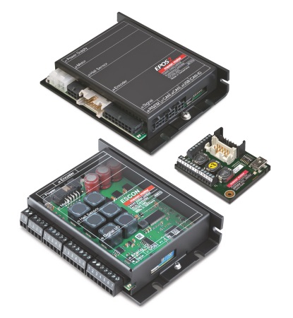
A motion control system is a system that controls the position, velocity, force or pressure of some machine. As an example, an electro-mechanical based motion control system consists of a motion controller (the brains of the system), a drive (which takes the low power command signal from the motion controller and converts it into high power current/voltage to the motor), a motor (which converts electrical energy to mechanical energy), a feedback device (which sends signals back to the motion controller to make adjustments until the system produces the desired result), and a mechanical system (including actuators, which physically produce the desired end result).
A Motion Controller or Automation Controller is the primary intelligence, or brain, within a motion control system. It is responsible for calculating and generating the output commands for a desired motion path or trajectory. Motion controllers vary in complexity; sophisticated motion controllers typically consist of a trajectory generator (path planner), interpolator, and control loop for servo motor control.
Types of Motion Control Systems
Open Loop System
A system that does not use feedback to verify the desired result, or output, has been reached. Most stepper motor systems are operated open loop.
Closed Loop System
A system that uses feedback to verify the desired result, or output, has been reached. As an example, a feedback device such as an encoder or resolver is commonly used to provide position or velocity information to a motion controller. A servo motor system requires the use of a feedback device.
Types of Motion Controller Topologies
PLC based motion controllers typically utilise a digital output device, such as a counter module, that resides within the PLC system to generate command signals to a motor drive. They are usually chosen when simple, low cost motion control is required but are typically limited to a few axes and have limited coordination capabilities.
PC based motion controllers typically consist of dedicated hardware run by a real-time operating system. They use standard computer busses such as PCI, Ethernet, Serial, USB, and others for communication between the motion controller and host system. PC based controllers generate a ±10V analog output voltage command for servo control and digital command signals, commonly referred to as step and direction, for stepper control. PC based motion controllers typically are used when high axes count and/or tight coordination is required. The drawbacks of this topology include complex cabling and potentially long wiring distances between the drive and motor.
A
Fieldbus is an industrial computer network system used for real-time distributed control of industrial machines. Programmable Fieldbus Controllers are typically used to connect multiple devices within a manufacturing plant. The four basic fieldbus networks are: sensor bus networks, device bus networks, control bus networks and enterprise bus networks. Fieldbus networks allow for daisy-chain, star, ring, branch, and tree network topologies.
A fieldbus based motion controller topology consists of a communication interface device and intelligent drive(s). The communication interface device typically resides within a PLC or PC system and connects to a single or multiple intelligent drives. The drives contain all the functionality of the motion controller and function as a complete single axis system. Often the drives can be daisy chained to other intelligent drives on the same fieldbus. The benefits include all digital communication, detailed diagnostics, reduced cabling, high axes count and short wiring distance between the drive and motor. This topology has a higher cost especially at lower axes count and has limitations providing tight coordination for multiple axes. Examples of this topology include Profibus, DeviceNet, RS-232/485, and others.
Asynchronous vs. Deterministic Topology
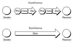
Asynchronous communication is the transmission of data, generally without the use of an external clock signal, where data can be transmitted intermittently rather than in a steady stream. Asynchronous literally means not synchronous, meaning, data is not transmitted at regular intervals, thus making possible variable bit rate, and that the transmitter and receiver clock generators do not have to be exactly synchronised all the time.
Deterministic communication is the transmission of data reaching its destination in a specific, predicable time. Time critical data transfer must be guaranteed within short and precise configurable cycles, while less critical data can be transmitted in asynchronous time slots. Data reaching its destination at guaranteed times are critical for motion control.
A deterministic bus based motion controller topology splits the motion controller functionality across a communication interface device and intelligent drive via a deterministic digital network. The communication interface device typically resides within a PLC or PC system and contains the trajectory generator. The intelligent drives typically contain the control loop and interpolator and can be daisy chained to other intelligent drives on the same network. The digital network is deterministic with low jitter to allow for tight coordination in multi axes applications. The benefits include all digital communication, detailed diagnostics, reduced cabling, high axes count, tight coordination, and short wiring distance between the drive and motor. This topology has a higher cost especially at lower axes count. Examples of this fieldbus topology include EtherCAT, SERCOS, Ethernet Powerlink, PROFINET IRT, SynqNet, CANopen, and others. These types of fieldbuses are also referred to as Distributed Control Systems.
A
Distributed Control System (DCS) is a control system for a process where the individual control elements are not localised. The system is made up of several control elements organised into a hierarchy which are all connected to a central communication system for monitoring and control. When building a DCS system, it is important to consider all aspects of the system, from the I/O to the PLC, the motion element and the supervisory HMI. DCS systems often use a central PLC connected by network cables to nodes which contain I/O devices such as: fieldbus couplers, I/O slices (usually input/output, or digital/analog), and terminal blocks.
For more information on maxon’s controller range please contact us on 01189 733 337 or salesuk@maxonmotor.com.
© 2017 by © maxon motor ag
Back to the news overview


